Op-amp
home
back to amplifiers
back to solid state amplifiers

 Op-amp based amplifier designs contain less VISIBLE amounts of components but one has to remember that those tiny chips, even those with just a few pins can have extremely complicated high performance circuits inside it. Even using components with say multiple emitters that do NOT exist in discrete components. Not all op-amps are suited for audio amplification. This is because certain properties may not be desirable for audio reproduction, such as relatively high noise levels, low power supply voltage limits, low output current capabilities, limited frequency range, slow speed (slew-rate) or settling time (time it takes for an output to become stable after a change in input voltage) to name but a few.
Most audiophiles like to swap out (roll) op-amps but this may not always be the wisest thing. An op-amp that performs well in circuit ‘A’ for instance, may become unstable or perform poorly in circuit ‘B’ and vice versa.
Subjective found differences between op-amps can usually not be shown to exist in (blind) comparison tests, with perhaps the exception of their behaviour when operating OUTSIDE their intended operational specifications.
When op-amps are used as output devices (that directly drive low impedance headphones) these limits are reached quite easily.
The most common shape of op-amps is the DIP-8 housing can hold 1 or 2 independent circuits. Some housings can have even 4 independent sections but these have either 14 or 16 pins. The most common op-amp based amplifiers are the well known battery fed portable amplifiers such as the well known C’Moy.
As most circuit boards use SMD (surface mount devices) you will find many of the op-amps shown on the right.
Not all of those 8-pin devices are op-amps though. Regulators, rail splitters, charge circuits, SMPS circuits, or other special functions can use the same ‘enclosure’.
Here you can view/download a VERY extensive test of various over the counter op-amps and discrete op-amps. If you are interested in technical performance of op-amps this is the best work I have come across.
Some tests about performance of these designs (they are actually about the simplest designs you can build) are found here. These are generally DIY projects but off the shelve products are available as well. Brands like ‘Neco, JDS labs and the cheaper ‘Zigis’ or Chinese offerings may work well also. More complex and better performing products using op-amps exist also and one of the better commercially available ones is the O2 amplifier.
 Op-amps consist of the same basic building blocks as that of most amplifiers. A voltage and current amplification stage in one, represented by the 2 blue triangles shown on the left.
They have 2 inputs. 1 positive (non-inverting) and negative input (inverting). Op-amps have VERY high amplification factors (in the thousands to millions). In order to use them as proper amplifiers with excellent bandwidth and distortion pcharacteristics and sensible gains between 1x and 10x for instance a feedback circuit (green block on the left) MUST be applied. Feedback usually consists of 2 (or more) resistors and in certain cases capacitors that may be needed for stability or to create filters or limit bandwidths. Op-amps usually cannot provide high output currents nor are they designed to be used that way. For most op-amps output currents are limited to around 30mA to 50mA but some can even manage 100mA or even 300mA. Specialised output devices also exist that can reach up to 1A output current. Higher power (current) ‘op-amps’ are also available but these are more like specialised power amplifiers with different housings and when mounted on big enough heatsinks these devices can deliver up to 100W in loudspeakers. These components, however, cannot be described as real op-amps any more. For delivering power hybrid modules also exist that have several pins that also need external components to function as an amplifier but they are basically discrete amplifiers build on a single (small) ceramic ‘substrate’.
 Op-amp based amplifiers are generally easier to design and build than discrete designs and can have high levels of performance in many ways except for maximum power output although designs exist that can deliver higher than average output power levels. Some DIY designs can be found in the DIY amplifier section. such as C.H.AMP, Headphone amplifier with OPA627 and BUF634, Portable headphone amp with OPA2134, Zigis portable amp.
a simple C’Moy amplifier with DIP-8 TLE2426 rail splitter
Below a picture of an op-amp amplifier (C.H.AMP) that has several possible settings and is thus configurable.
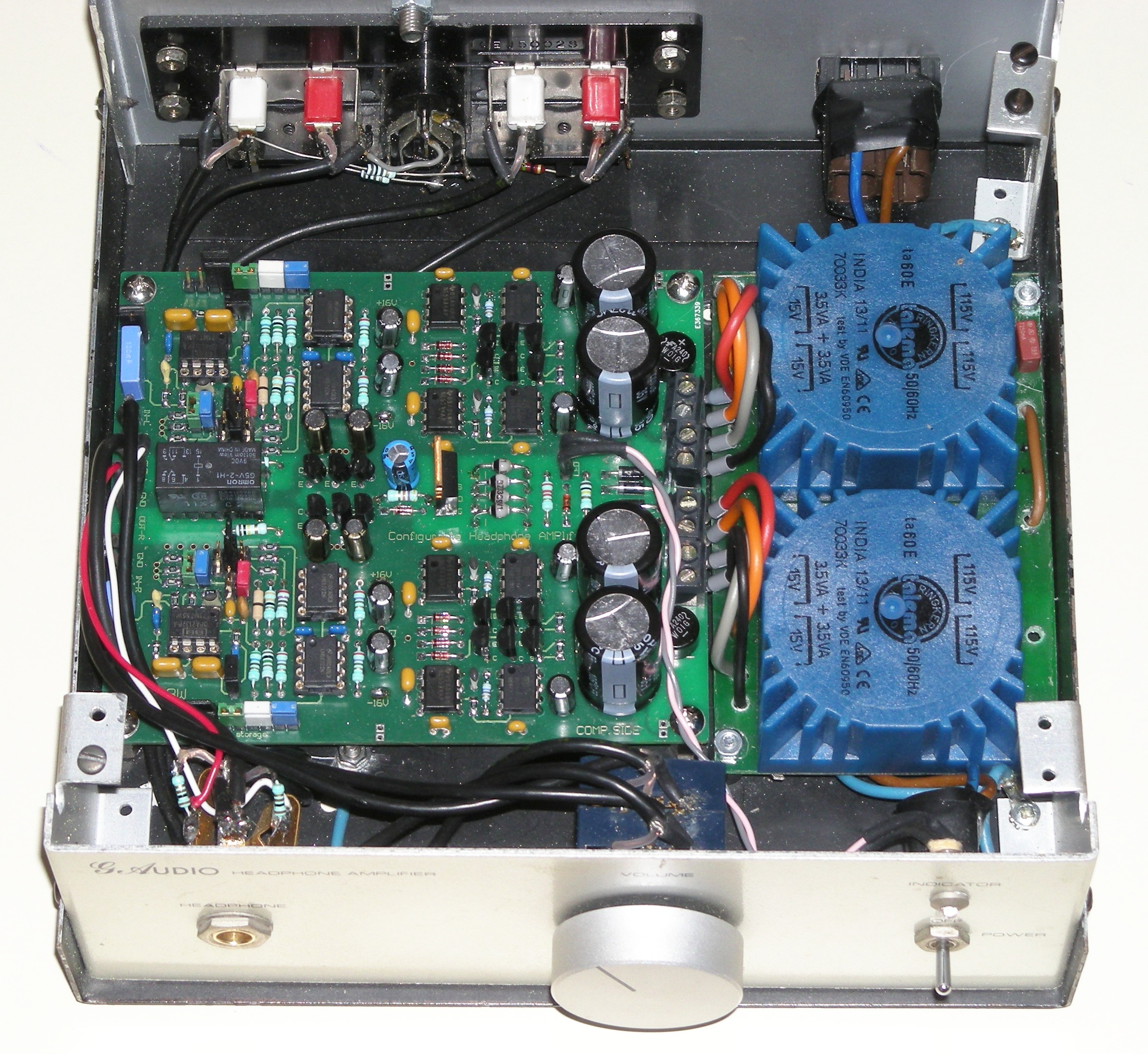 It uses 2 dual op-amps as output devices (thus in total 4 op-amp- ‘sections’) in parallel to increase the output current to above decent levels.
Also the power supply is made with op-amps to ensure a low noise and low output impedance power supply section in dual mono construction.
The keywords for this design is safety (output power is limited to around 200mW) and the fact it can be easily configured to match with lots of headphones.
When using a LOT of op-amps all working in parallel you can even increase the output CURRENT to levels where one is able to drive speakers with it.
below a picture of a design I made about 30 years ago.
A Loud Speaker amplifier made up from a huge amount of op-amps.
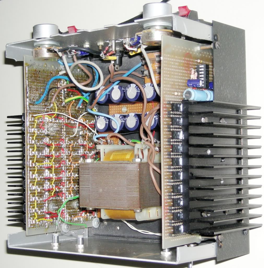
The used op-amps were driver L272M IC’s salvaged from old Technics SLP202A CDM4/19 driver boards from the laser assembly and by themselves could deliver 1A per output. In unity gain follower mode it had a Power bandwidth well over 250kHz and could drive 4Ω speakers with ease.
There is also a hybrid form of amplifier that fits neither in all opamp but also isn’t made of discrete components alone. These designs are never called hybrids though, this term seems to be used for tube/SS designs.
In most designs the input stage is made of an opamp and the output stage is made of discrete components (FET’s or transistors) in order to increase output CURRENT capabilities of the circuit. More often than not overall feedback is used to ‘remove’ the non-linearities (crossover distortion) in these output stages.
Below a design that uses a discrete input stage that is made to perform ‘badly’ in the harmonics generating department.
A J-FET is used which works quite similar (but not exactly the same) as tubes. The output stage is formed by an op-amp that can deliver a high output voltage AND more than enough current to drive ‘difficult’ headphones.
The design is called ‘project Polaris‘ and has some properties that are configurable by the user.

Here is a review for the Zigis Portable Amp which is sold on e-bay. This is a cheap ‘C’Moy’ type amplifier that performs well and is an upgrade from many of the ‘onboard’ amplifiers of portable equipment.
Review of O2 Headphone Amplifier. A battery operated amplifier that delivers a lot of power to enable bigger headphones to be driven with less problems.
home
back to amplifiers
back to solid state amplifiers

Are you gona release that loud speaker op-amps design details?
I have never drawn the schematic for it. It is just a simple non-inverting gain stage + phase inverter (-1x gain) on its output which creates a balanced signal.
These outputs are driving a bunch of L272M in follower mode where each output opamp has a 1 ohm resistor in series and the outputs of these resistors are combined.
18×2 = 36 opamps for 1 amplifier half.
This made the output R of the bridged amp about 0.06ohm (DF approx 60 for 4 ohm and 120 for 8 ohm)
This way a bridged amp is constructed that could supply 50W in 8 ohm (+/-13V rail supply voltage) and 75W in 4 ohm (transformer was the limiting factor).
Sometimes, out of the blue it blew an L272M taking along a few others with it. Had to disassemble it and pull each opamp and see if it was fried and replace the broken ones with new ones.
When this happened again after a few years and ran out of opamps I shelved it.
It was a fun experiment.
first of all, im in high school and i only know the ohms law and some other resistor laws and basics. my soldering skills are great, but i dont know how to design circuits so please help in it, and maybe i can learn from it.
Someone also made something similar it seems:
https://ggianluca.wixsite.com/opamplifier
I used higher current capable and more opamps and made it bridged but basically the idea is similar.