Rectifiers
home
back to learn
back to power supplies
published: Jun-17-2015, updated: Mar-16-2017
Rectifiers, how do they work.
A rectifier consists of 1 or more diodes and a reservoir capacitor, a.k.a. smoothing capacitor. It is used to change A.C. (Alternating Current) voltages into D.C. (Direct Current) voltages. The upper picture shows a half-wave rectifier, the bottom picture a full-wave (bridge) rectifier.
The full-wave rectifier has a higher efficiency and lower ripple voltage as the reservoir capacitor is charged more often as both halves of the sine wave are used.
 Rectifiers are used in linear power supplies preceded by a transformer that has lowered the voltage. The AC voltages are sinewave shaped.
In SMPS Rectifiers are used to rectify the mains itself. That voltage is used to create a higher frequency AC signal (NOT sinewave shaped in most cases) which is fed in a much smaller sized transformer and rectified again.
For 50 (and 60Hz) you do not need high speed diodes. For rectifying the very frequencies/wave-forms in SMPS high speed diodes are essential.
Instead of explaining how a diode rectifier works I will simply link to a wiki about this subject.
Since this forum is about headphone amplifiers and not power amplifiers to drive loudspeakers and most electronic equipment used in audio reproduction does not consume high power levels either this article is only about power supplies used in low power and low voltage equipment. Essentially higher power equipment works similar but with higher voltages and most of all higher currents. The principle is the same though.
Most people think their equipment is continuously connected to mains but actually it is not. Only when the voltage peak of the AC sine-wave is higher than the voltage on the reservoir capacitor a current will flow. The rest of the time the diodes actually do nothing at all. On some forums people claim the power that is consumed by the speakers and amplifier is directly drawn from the mains. This is a wrong statement. The reality is that the needed power is drawn from the reservoir capacitors. The reservoir capacitors are replenished by short pulses drawn from the mains.
So … Even though it is often said that all drawn audio power is coming directly from mains and that audio signals are thus also drawn/present from the mains (and in the mains cables) is thus complete and utter NONSENSE.
All audio currents are drawn from the reservoir capccitors and or outputs of regulators ALONE.
In audiophile circles it is common practice to swap out ‘slow’ rectifier diodes for high speed Schottky diodes that are intended to be used in SMPS. This action always seems to perform miracles for the sound quality especially if they are ‘snubbered’ as well. A snubber is a capacitor (+ small resistor) in parallel with the diode and is used to prevent High Frequency emissions (extremely small) and to ‘short’ HF voltages entering the rectifier. It essentially slows down the super fast properties of that high speed diode and creates a solid bridge for HF signals.
A diode acts like a ‘switch’ that takes a minimal voltage of around 0.5V to 1V. It takes a very short time to turn ‘on’ (think a few ns). Once it is on it has a very low ‘resistance’.
Lets say 2A average runs through it at 0.7V which is 1.4W during the time it is on, the rest of the time it can cool off as it does nothing.
When the input voltage drops below the 0.7V again a diode doesn’t switch ‘off’ immediately. This takes some time called ‘recovery time’ for Schottky diodes this may be between 10ns to 100ns. For the standard 1N400x series the ‘turn-off time’ is around 500ns.
When a ‘normal’ diode is used in a switch-mode power supply at a high speed, think towards MHz instead of 100Hz for rectified mains, and the input voltage of the diode has a negative voltage on it of say 15V because the converter’s output voltage switched polarity really fast as it is close to a squarewave in character instead of a sinewave (say within 20ns) the diode does not have time to switch off and thus conducts (during that few hundreds of ns) allowing a very high REVERSE current that can exceed the 2A and draws from the reservoir cap which just had been charged.
The fact that the diode has -15V reverse voltage on it makes the ‘peak power’ >30W for that (very short) time period.
Needles to say that in these switch mode power supplies diodes need to be used that switch off VERY fast. Preferably faster than its input voltage switches polarity.
A 500ns diode wouldn’t even act as a diode anymore for a relative long time period but act as a ‘short’ that heats up very quickly. It would blow !
So the faster Schottky diodes are purposely designed so switching frequencies can be higher.
The reason why manufacturers WANT higher switching frequencies is because reservoir capacitors can be smaller in value and above all the HF transformer can be much smaller in size. Smaller means less material and thus cheaper.
More powerful and smaller power supplies can thus be constructed.
In the audio world it is common to replace ‘normal’ diodes with faster ones and miraculous improvements have been assigned to this simple to do mod.
Let’s have a look at the 50Hz transformer. Each rectifier diode switches on each 0.01sec for about a few ms and then switches off again.
The input voltage of the rectifier is a sine-wave which varies VERY slow over time (that is from a hypothetical diode’s p.o.v.)
In fact the slew rate of the input voltage of a 12V AC rectifier to go from +18Vto -18V takes about 10ms (when we assume a triangle waveform) .
So in 10μS it drops about 3V (actually even less as the voltage drop on top of a sine-wave is slower).
In 1μs it drops < 0.3V and in 500ns it drops < 0.1V.
So the ‘slow’ 1N400x diode (with its 500ns recovery time) is already switched off completely when the forward voltage dropped from 0.6V to 0.57 Volt.
Thus a faster diode doesn’t have any benefits for 50/60Hz power supplies, simply because there are no fast reverse voltages present.
100Hz (rectified 50Hz) sine-waves are so incredible slow ‘moving’ compared to the diodes (even ‘slow ones’) that for the diode the turn-off time is instantaneous.
As there is NO audio going through the mains transformer/diodes (only very short current peaks to charge the reservoir capacitors) there can be no sonic benefits at all.
Most of the audiophile claims are based on subjective findings. It is hard to find any info regarding currents, voltages, frequencies and speeds present in audio equipment and this article will address these aspects so it is clear about which quantities we are talking about and shed some light on the validity of the claims.
The reservoir capacitor is only charged for a relatively short period, namely about 1 to 5ms (milli seconds) every 10ms, assuming full bridge rectifiers are used at 50Hz mains frequency . The current the reservoir capacitors are charged with is limited by the voltage difference between the input of the diode and the (at that moment) voltage of the reservoir cap and the dynamic resistance of the diode and above all the power rating of the used transformer. The dynamic resistance of a diode is roughly calculated as 1/(40 x I diode)
The reservoir cap’s charging current is limited by the internal resistance of the transformer. That is, the resistance of the secondary winding AND transformed losses of the primary winding as well as the losses in the magnetic field and the bandwidth of the transformer. The ESR (Equivalent Series Resistance) of the capacitor is much smaller in value and thus of little importance as in a series circuit the current is determined by all resistances added. Adding a small one to a bigger one doesn’t really change the value much.
The circuits that draw the power do this constantly and/or dynamic depending on current consumption by driving audio or varying processor loads. That drain is mostly coming limited by a regulator circuit that is between the reservoir cap and the actual circuit that needs to be supplied with a constant voltage. Since rectifiers are ‘off’ most of the time the reservoir capacitors (hence the name) act as a reservoir where the needed current can be drawn from. Every 10ms that capacitor is recharged again during only a few Milli-seconds. The constantly slightly varying voltage level (from highest charged level to a lower level right before the capacitor is about to be recharged is called the ripple voltage. The amplitude of this ripple voltage depends on the current drawn, the capacitance of reservoir cap and the frequency it is being charged (50Hz, 60Hz, 100Hz or 120Hz). The lower the current drain, the lower the ripple voltage. The bigger the capacitance the lower the ripple voltage. The higher the frequency the lower the ripple voltage. This last bit is important for SMPS as the frequencies are many thousands of times higher than those in mains. Below the same circuit (transformer, capacitors, diodes) but a different current draw. In the drawing the upper trace has only 0.2V ripple voltage and the lower trace 0.88V.

The interesting conclusion of all of this is that the current drain, and thus power consumption, of the circuit being fed is (more or less) constant BUT the reservoir capacitor is not fed constantly but periodically every 10 or 20ms depending on the type of rectifier used and assuming 50Hz mains frequency. The power drawn from the load must thus be replenished in a shorter time than it is being drained. Because the voltage of the reservoir cap is rather constant this can only mean the momentary peak current through the diodes is (significantly) higher than the constant current drawn out of the reservoir cap.
Showing what this looks like in practice with actual values, as can often be found in audio equipment, is a matter of simply conducting some real life measurements. Some of the oscilloscope images below are made with practical values and some had to be exaggerated to show what is essentially going on.

To make things a bit more visible I used a half-wave rectifier (just one diode) as shown in the schematic above which is more of a worst case scenario than when a full-wave (bridge) rectifier is used. With a full-wave rectifier the currents and ripple voltages are a factor 2 smaller.
A Silicon diode and a reservoir capacitor of 3300μF is used. The value of the reservoir capacitor is quite realistic. The load is a 33Ω resistor and the used transformer is 50 Watt. Waveform shots are also taken using regular diodes (1N4001 in this case). It is pointless to show plots using Schottky diodes as well as, aside from a 0.3V increase in output voltage, they are indistinguishable in current waveform.
 The upper trace shows the reservoir capacitor voltage and the lower trace shows the diode current. The load draws a constant 0.42A and since the voltage is 14.4V (average) this is a power consumption of about 6.5W.
The on-time of the diode is 3.5ms every 20ms. This means all the power drawn in 20ms time needs to be replenished in 17% of that time. Because the charging current rises relatively slow and also drops slowly the peak current will be higher than the average current. Peaks of 3.7A are thus needed to be able to provide a constant drain by the load of about 0.42A. The ripple voltage is 2 Volt in this case (about 14 % of the average voltage) and the diode reaches its peak current in about 1.2ms. The frequency component in the ripple is about 1kHz. This can be heard as a ‘sharp’ hum when one was to listen to it. It is painfully obvious using diodes with rise times in the range of a few 100ns (thus over 1,000 x faster than the present rise-times) and is more than sufficient to ensure the current can rise this fast and using faster diodes running in sub-ns is therefore pointless. Consider mains transformers usually cannot supply current/voltages at frequencies above 10kHz this means rise-times are limited by the transformer to about 20µs anyway.
Because the charging current is limited by the transformer it is obvious that when the power rating of the transformer is increased the current can also increase and the on-time will be shorter. When a transformer with a lower power rating is used the currents decrease and the on-time increases. Below a picture of the same rectifier circuit with the same load but the transformer is 6W in this case.
 The output voltages of the transformer used in UNLOADED condition is not the same and thus not 100% comparable but the general idea can be seen. Power consumption is 2.3W in this case. Note the ripple is less ‘sharp’ and thus contains less harmonic contents (<100Hz).
What happens when power levels are much higher ?
Below some similar measurements with a 160VA toroidal transformer with 2 windings of 25V each.
 The first plot is made with a half-wave rectifier (1 diode) on a single winding with a 15,000 µF/100V capacitor and a 7.5Ω load as shown in the schematic above.
 The AC input voltage on one winding was measured at 23Vrms while the rectified DC voltage measured 22.8V.
The 7.5Ω load resistor created a 3A current and thus the load is 70W.
The capacitor’s charging current was limited by the transformer.
Peaks of 20A were needed to replenish the drawn energy in 1/4 of the cycle period.
The rise-time already shows that the current takes 2ms to rise from 0 to 20A (the given rise-time in the plot is calculated between 30% and 70%).
When we write this down in nanoseconds the rise time is 2,000,000 ns … are fast diodes of < 100ns really needed to ‘follow’ the currents ?
Another interesting thing is the frequency spectrum of the currents flowing through the diode and thus transformer as well.
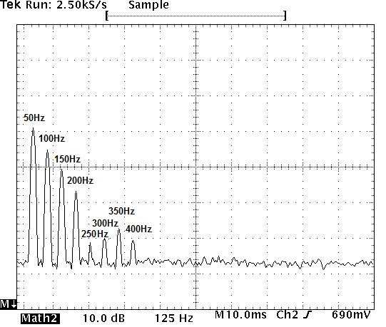 Most of the incoming current spectrum is between 50Hz and 200Hz.
The higher harmonics are caused by the flattening of the input current.
From 250 to 400Hz some energy is present as well. Above 500Hz there isn’t any contributing current present.
When we connect the second winding in parallel via a second diode the maximum current increases somewhat because the resistance of the secondary windings are now halved.

The current doesn’t increase by a factor 2 but only by 20% because the primary winding is the one doing most of the current limiting.
The DC output voltage increases to 24.9V and the load current increases to 3.3A, the drawn power by the 7.5Ω load is thus 82W.
This is also an increase of around 20% just like the ripple voltage to 4.4V.
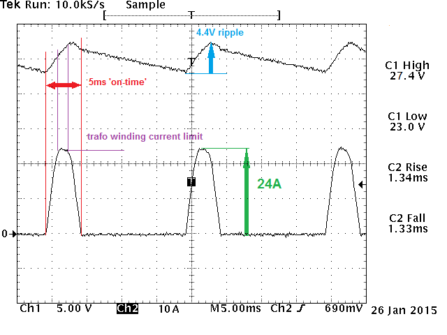 Because the current has increased the capacitor is replenished slightly faster but also has to rise an extra 20% in voltage as well (the ripple voltage). The extra power that is available because of the added winding decreases the ‘on-time’ of the diode from 5.5ms to 5ms.
As the rise time is a bit shorter the frequency spectrum of the current changes as well. Harmonics now reach up to 450Hz.

The examples above are all made with a half-wave rectifier so a ‘worst case’ scenario unfolds concerning ripple current and diode currents.
Normally full-wave rectifiers in either dual winding + 2 diodes or a single winding + bridge rectifier is used for creating a DC voltage.
Below the schematic of a full-wave rectifier. It differs from a single secondary winding circuit using a bridge rectifier but the currents are the same.
 In this case the capacitor will be replenished twice as often and the transformer is loaded more ideally as now both halves of the incoming sine-wave are used to feed current in the reservoir capacitor. In the half-wave situation only one half of a sine wave is used as the name already suggests.

In the plot above we can see the voltages and currents present in the full-wave rectifier circuit. In this case 2 windings in series and 2 diodes are used to create a full-wave rectifier.
It is obvious that the capacitor is being replenished twice as often (in a 1:2 time ratio) where in the half-wave rectifier situation the ratio is 1:4.
This also means that the DC voltage doesn’t drop as much anymore which is clearly shown by the ripple voltage being decreased from 4.4V to 2V.
The DC voltage measures 26.9V and the load current is 3.55A. Power consumption is now increased to 95W.
But the diode currents have reduced to half the value as well and are still far below the current limit capabilities of the transformer.
The peak currents are now 12.5A instead of 24A. This means that, when a higher ripple current is allowed, the power that can be drawn from this type of rectifier is much higher as the current needed to replenish the capacitor can still be increased.
The frequency spectrum of the charge currents also changes drastically.
The main frequency is now doubled to 100Hz and there are less harmonics present. This also means less ‘pollution’ of the mains.
 Till now only the currents in the rectifier diode(s) are shown. Of course the rectifier is fed by a transformer that lowers the mains input voltage (115V or 230V) to 25V in this case.
The power in the secondary and primary winding of a transformer are always (closely) the same (there are some losses in the transformer that are discarded here) .
When power in the transformer remains the same and the voltage is lowered this means the current thus increases on the secondary side by the same factor as the voltage decreased.
For countries with 230V or 115V mains voltages the drawn power is the same but the transformer ratios differ.
the transformer voltage ratio of the 230V transformer used in the measurements above is 230/25 = factor 9.2.
When looking at the primary side of the transformer, in relation to the secondary side where we measured we the voltage, the voltage is a factor 9.2 higher so when the power remains the same the current in the primary side is a factor 9.2 smaller.
For 115V mains systems things differ of course: In this case the voltage ratio of the used transformer is 115/25 = factor 4.6.
When the power remains the same the current in the primary side is a factor 4.6 smaller.
When looking at the currents drawn at the primary side of a 230V transformer (thus mains side) when drawing 82W from a single-wave rectifier, we will see current peaks in the primary side of 2.6A. For 115V mains those currents will be 5.2A.
When looking at the currents drawn at the 230V primary side (thus mains) when drawing 95W with a dual-wave rectifier we will see current peaks of 1.4A. For 115V mains those currents will be 2.7A, this is assuming the mains frequency is 50Hz.
Of course for 60Hz regions the capacitors will be replenished 20% sooner than for 50Hz regions so the currents will be a bit smaller for 60Hz regions but not exactly 20% lower as the charging time also decreases which in turn increases the current.
I suspect the peak currents to be about 10% smaller for 60Hz regions than the numbers quoted for 115V/50Hz.
In short:
Using regular (Silicon) diodes and bridge rectifiers is good enough.
A reason to use Schottky diodes instead of normal ones could be if a little more voltage is needed. It is important to select LOW voltage drop Schottky diodes in this case as not all Schottky diodes have equally low forward voltages.
It is completely pointless to select fast diodes with soft recovery for mains rectifiers. The word ‘fast’ may well give you the idea that peaks in an amplifier are improved and the word ‘soft’ may give someone the impression the sound may be smoother though.
Alas the speed and ‘soft recovery’ play NO role here.
When changing transformers to higher power versions you need to know if the diodes can handle the higher PEAK currents that may occur.
Make sure the rectifier can handle peak currents that exceed the constant drawn current at least by a factor 10 so if possible use high current bridge rectifiers, not the ones that can just handle the maximum currents drawn by the load !


Just wanted to leave a comment as no one else has and this article deserves some love as it is well written and makes a number of excellent points.
Thanks!
What audio equipment do you listen to? Have you done any subjective tests to verify your opinions, and are you saying because you can’t tell the difference therefore there is none?
I am sorry if my measurements and conclusions do not match your (and those of others) subjective findings.
There is really not much I can do about that discrepancy.
Generally I listen to music and not the equipment. Both can be quite varied.
ultra fast soft recovery diodes in bridge rectifiers with AC at 50/60 Hz. There is debate about the relevance of this and if the use of these diodes help improve sound quality in audio applications.
A subjective view point of improved sound quality is not to be dismissed. For many people high end audio equipment is pointless as they do not consider it to be of any greater performance than mass produced units found in electrical stores also selling toasters and washing machines.
I have noticed the many graphs and performance curves in this article, but, none have revealed the effects of varying diode types on music wave forms. an ultra fast soft recovery diode will be less “visible” in the circuit due to there being much less switching noise and it is this switching noise that becomes a component of the musical wave form. The reproduced music now has an electronically produced component added to it. With fast/soft recovery diodes this component is reduced by quite a degree.
Fast diode switching may be considered unnecessary for 50/60 Hz applications, however, the point of rectification is converting alternating current to direct current. This direct current needs to be of battery like quality with absolutely no notches, fazing or as the correct term is have no AC component whatsoever. A fast switching speed with much lower switching noise will only help achieve this goal. Note the term “smoothing capacitors” as used after AC rectification to DC.
The use of smoothing capacitors is well understood. To smooth out the AC component of DC and this is made easier for capacitors to do if fast switching diodes are used in the rectifier. A subjective understanding of improved amplifier sound quality with the use ultra fast/soft recovery diodes can be a revelation for the listener. It’s like now being able to see the wood for the trees. Once experienced there is no going back to standard diodes.
Diode switching noise is not present across the smoothing/reservoir caps, it is only present on the input side of the rectifier, thus not after the rectifier diode.
Switching noise of rectifiers can quite effectively be removed by proper snubbering of the transformer or diodes (requires a resistor + capacitor to damp this).
Of course, if changing rectifier diodes will bring forth more sonic enjoyment for people with very acute hearing then I am all for swapping out diodes.
They don’t cost much and if they bring more ‘peace of mind’ I don’t see any reason not to use them.
There just isn’t a technical explanation for it.
Your technical assessment of what soft recovery does/means/works, however, seems more based on the will to explain an (unmeasurable ?) phenomenon, i.e. sound quality improvement/change, by linking perceived sonic improvements/changes to certain aspects of diodes rather than factual information about this subject.
If you know of any information or measurements that undeniably shows fast diodes in mains rectifiers actually results in a different analog/music/test-signal waveform then I would appreciate a link or reference to such research.
I was also curious about this diode recovery business. Inserting a current monitor into one arm of a 50Hz operated bridge rectifier made with 1N4004s and followed by 4700uF capacitors results in easily visible turn off reverse current flow and a subsequent recovery-to-zero rise time of about 2uS. Use of UF4004s pretty much removes this affect. I had previously noticed low amplitude glitches of 1uS or so appearing on a scope when I lifted the signal pin of a probe I was using on a headphone amp I was developing. I have also noticed major differences in current ringing with different types of 50/60Hz power transformers. One I tried rings a lot at around 3-4KHz. Another, intended for audio equipment and also, incidentally, copper-screened, shows no visible ringing. EM coupled interference is definitely a possibility, albeit at low level. I have some scope captures for both effects if you are interested.
Not having test gear limits confirmation of my thinking. However some 20 years ago I was on a test and debug team in a factory manufacturing power station control equipment.
This gave me a good understanding of how component related artefacts have an impact on circuit performance.
I can still use this experience to help me with improving circuitry. Have you tried potted power transformers?.
I will check for currents in the AC side of the rectifier. That is where said pulses can be found.
Snubbering helps here.
The reverse currents are only on the primary side and not present in the DC side at all.
The only way they can get into the audio-signal part (or DC line but only as common mode signal) is by a poor PCB design, wire layout, grounding scheme, by air or induction in wiring that is running way too close to the transformer wiring in that case.
The pulses would have to be substantial for that too happen.
I would not put it past a few manufacturers to have a poor designs here and there.
The question remains whether or not such pulses would become audible as a ‘sharp’ hum or a modulated 3-4kHz (or whatever frequency it resonates without proper snubbering) or would cause sound to be ‘degraded’ in performance somehow.
This is why I am very weary of claims of improved audible performance when replacing diodes.
There has to be a poor design in that case and even a simple program as RMAA should clearly show a measurable improvement even on crappy sound-cards if it was that bad.
Such a signal would also clearly show up in noise and distortion measurements as well.
Aside from the pictures of those reverse currents do you also have audio noise floor plots indicating something like that has entered the audio path ?
Would like to see those measurements and whenever I have some time to check a few diodes and transformers again will have a look in the spectrum between traffo and rectifier and traffo and mains.
Those signals would be very small though.
I haven’t seen these signals in various EMC/RF tests done where LPS were used without any additional filtering using ordinary rectifiers though.
Diodes have switching noise and take time to switch. This easily demonstrated on an oscilloscope.
To reinforce this is a signal diode such as the 1N4148. It has a switching time of around 4ns. This is an extremely fast time compared to a rectifier diode. Understanding the reason why signal diodes are fast switching is critical in understanding why fast soft recovery rectifier diodes are more desirable in audio power supplies.
One should not listen for what has been added to the audio signal, music, if faster, soft recovery diodes are fitted to a piece of audio equipment’s power supply, but, what is missing. What will be missing is the electronic “signature” caused by standard rectifier diodes. The sound will be easier to listen to and less fatiguing.
Diodes that have faster switching with reduced switching noise will be less “visible” in an audio circuit. Indeed some of these diodes are known as “stealth” diodes.
Exactly that is what I was debunking. After the rectifier there is NO difference at all in the DC voltage, regardless of which type of diode is used.
I have not seen it on an audio-analyser connected to the power rails nor heard any differences.
It is easy to build the power supply sniffer which can show easily how noisy a power supply is.
The DC voltage simply isn’t any different.
As stated in the article. These fast diodes are made for a specific purpose in switch-mode power supplies.
Click to access how+to+check+your+power+supply+for+noise.pdf
Of course, when using diodes with another Vf the DC voltage level will be different.
When you have any objective information (ripples or signals being smaller on the smoothing caps) then I would be very interested in seeing those plots.
Hi, Not hearing a difference can be down to many reasons. Though no difference in DC voltage is expected and yes fast soft recovery diodes are intended for switch mode power supplies.
However, a diode that is faster switching with much less switching noise will be less noticeable in audio equipment. Power supply capacitors tend to pass this noise on to the rest of the circuit and will be heard by effecting the audio signal.
Yes, snubbers can be used to reduce noise but prevention is better than cure.
I have replaced standard diodes with fast diodes in many audio instruments and have always noticed an improvement. If I hadn’t noticed an improvement in the first piece of audio gear, a cd player, I converted I would not have bothered continuing with other gear.
Noise is noise is noise and if its removal is not noticed audibly then maybe time should be taken to really learn the audio gear that has been converted to fast/soft diodes. As I said earlier if I hadn’t noticed an improvement then I would not have carried on with other gear. I’ts just that with the cd player as soon as I put a cd in and pressed play the difference was immediate and definite.
Do you have any plots or measurements showing the DC power supply rails are any cleaner or even different when using fast/soft recovery diodes ?
I haven’t been able to show any differences between these type of diodes in the DC voltage rails.
How do large smoothing/decoupling caps pass on noise where they in fact short (=block) higher frequencies and thus not pass them on ?
Only above say.. 100kHz to 1MHz (depending on the cap) the ESR starts to rise again which can be negotiated by paralleling 1uF ceramic ML caps for instance.
What voltage per division are you using on your scope?. It needs to be a very small v/division to see anything. When you start to see the AC component on the DC rail is when to look for noise and spurious stuff.
As for power supply capacitors blocking high frequencies; they don’t is the simple answer. This is done with the use of small value capacitors. Check out X and Y type caps. for mains filtering before the bridge rectifier. Evox Rifa do a good range.
I can remember testing power supplies for AC component being within tolerance. Power supplies having faster diodes, always had cleaner DC lines. Remember to have the scope at high resolution and focused to reveal all the gunge lurking on what at first looked like a nice clean line.
Also increasing the load will really wobble the gunge.
Going back to power supply capacitors filtering high frequencies. Take a look at all adverts for mains conditioning equipment on the hi fi market. If power supplies filtered high frequencies there would not be a market for conditioning equipment.
Do you actually have comparative shots (be them scope or audio analyzer) showing the differences between the diodes before and after the DC regulators showing this effect ?
Have you used something like the power supply sniffer to actually listen to the DC rails or to analyze them using a soundcard ?
Have you ever checked out ESR plots of smoothing caps ?
Have you ever purposely injected a few kHz in common mode together with the AC voltage ?
If yes, how much of this was still present on the smoothing caps ?
There is is term known as over kill or over the top or maybe O. C. D.. No I do not have plots but I do have a pair of ears and ears are by far the best way to confirm sound quality.
I have come across many people over the years who have all sorts of test gear but when it comes to using their ears they run and keep running. This is because they don’t know how to use them.
Go to concerts of all sorts, pop, r&b, country or classical and enjoy them, get experience and also audition audio gear at different price points remembering that music is to be enjoyed and felt.
I do not need a host of test equipment all I need are my ears.
A case in point from the past. Centuries ago when churches were built organ makers would do some measuring then stand in the middle of the church, clap their hands, listen to the sound, then toddle off to build the organ. Electricity had not even been discovered.
That’s why I asked whether you have tried the power sniffer circuit. You can use your ears with it to actually listen to DC power supply rails. You can also connect an ADC and record and analyze the DC and see down far below audible levels.
No differences were found using both types of diodes in (regulated) DC voltages by me.
One day I should redo this test and post the plots (spectrum etc.)
But you are certainly not the only one reporting differences, I just have not found evidence of it myself nor anywhere else. Only anecdotal.
There have been test results posted but it has been some time since I checked them out and can’t find them.
There is something I have been considering about listening to power rails. The standard diode switching noise may not be that audible in itself but will, as I mentioned in an earlier post, effect the audio signal with its “signature”. Therefore it is only noticed by its effect on the audio signal.
When standard diodes are changed for fast/soft diodes it is only then, on the audio signal, a change is heard.
I started to look at diodes out of curiosity and following on from feeling I could hear a clear sound output difference between two power transformers, both substantially over-VA-rated and both removed from the circuitry by about a meter. I then found one transformer ringing quite a bit as the diodes came in and out of conduction on one transformer and also noticed the sharp reverse recovery edge on the 1N4004 diodes, almost totally removed by using fast diodes, I said UF4004 but actually they were BYT03-200s. The UF4004s I tried in a CD player. Incidentally with the CD player I swapped out the DACs for the top grade linearity version (BB PCM63) and although THD is below -90dB even for the poorer grade, you can hear the difference quite easily in terms of refinement and detail, especially on percussion. These are well regarded legacy R ladder DACs.
With audio, I find you generally have to make numerous incremental changes, but if you do, after a while you can be surprised by how far you have come in terms of transparency, detail and refinement, if that is indeed what you are after.
Regarding subjective/objective, I think the brain/ear may not work in a way that is totally analogous to how we normally design and evaluate electronics. I feel I can hear differences where measurement differences would be very minor, with components and even cables. I have not put a spectrum analyser on my DC to follow all these PSU changes and doubt whether I’d see all that much. Anyway the active circuitry should reject most of that noise. The major differences with the transformers is probably down to the use of a voltage multiplier for the tube/valve stage.
Amplifiers sound far more different than measurement differences would lead you to expect. I recently compared a high end solid state DAC/Headphone amp at $2000 with a hybrid one at $6000. The difference in sound character was very obvious, I would think to nearly anyone. Yet both measure excellently compared to any headphone.
A good way to test amplifiers under actual load and with music is by nulling.
Any difference, be it euphonic or detrimenta, phase, time or amplitude related are captured.
I trust those ‘measurements’ a fair bit more than my ears and a set of measurements.
“I trust those ‘measurements’ a fair bit more than my ears and a set of measurements.”
Indeed.
Yet music is made for ears, not for measurement. Can you measure why one vocalist is more popular than another? No? Of course not. No piece of electronic testing kit comes close to unraveling the complexities and nuances of human hearing.
I’ve made many tens (30ish I quess?) of diode bridge upgrades on audio equipment – DACs, DVDs, Amps, pre-Amps. I have almost always, not always, but most times, heard an improvement and so have every person who I have made the upgrade for. Some have been quite remarkable.
Methinks you think you know it all, but really you don’t. Maybe you should pour yourself a cup of coffee, sit down and let your ears tell you what they hear, not not allow your ignorance dictate to your ears what they can and cannot hear.
Thanks for the constructive criticism.
I am glad this gives audible benefits for you and your customers, regardless where the perceived improvements originate.
In the end that’s what audio is all about. Whatever floats your boat and drains wallets to your content is fine and customers are happy.
I agree subjectivity unbridled has problems..sometimes you just aren’t in the mood to enjoy music, or your memory is not that good. But comparisons over a period of time have value. Nulling will show gross differences, but it seems to me that you can hear 24 or even 20-bit audio over 16-bit, even when the resolution is actually below the noise floor at 16-bit. I think the accepted measurements of frequency response and THD are not that good at determining sound quality. CD, particularly early CD, springs to mind.
The rectifier diodes may be (almost) completely switched off by the time the forward voltage drops to 600mV or so (regular silicon p-n junction) but the diode stores charge and my understanding is that this charge results in a reverse current surge well above the very small normal Shockley equation reverse leakage current. It is the size and envelope shape of this charge (I*T) removal we are discussing.