Amplifier
published: Mar-11-2013, updated Oct-17-2022

Headphone amplifier schematics designed by Solderdude:
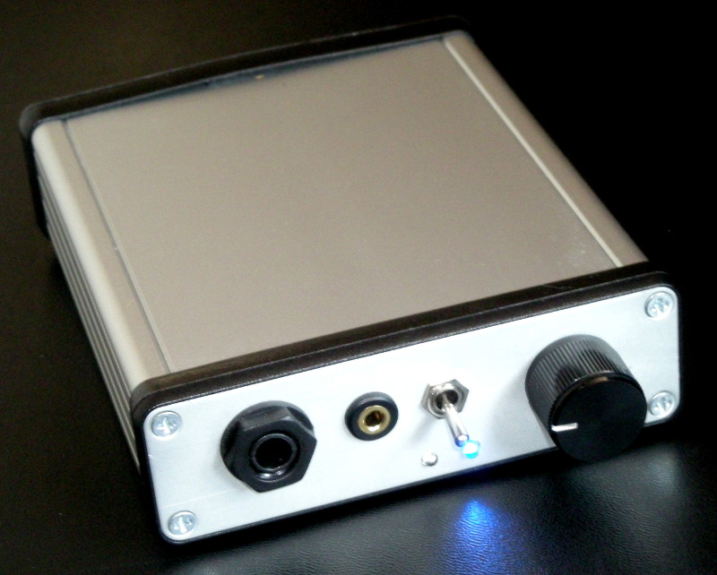
Below a (fully working) prototype of the desktop version (with the filter change top-lid open) + transformer
 Below the new Kameleon portable amplifier.
klick on the red links (project names) to view the schematics or article.
The Kameleon-2 portable headphone amplifier has some unusual properties.
 Above the prototype of the original Kameleon (sold out).
This portable headphone amplifier is designed around a very capable op-amp (OPA551) and accepts filter modules.
Each headphone will have it’s own plug-in module that corrects (as closely as can be done with simple analog filters) the frequency response of that specific headphone.
Not all headphones can be corrected (or corrected well enough) but the better ones often can.
Of course the amplifier can also be used without a filter module and can act as a powerful portable amplifier with selectable gain and or bass boost for instance.
The amplifier is discussed HERE in this thread in our FORUM. If you are interested in either bare PCB’s, kits or build amplifiers also have a look at the thread in our forum. Is your favourite headphone you want to use not (yet) listed in this ARTICLE) then ask if it is possible to make a correction for that specific headphone in the FORUM.
This amplifier is a spin-off from the headphone correction filter PCB.
(own design, built project, PCB’s and finished products are available, check the thread in our forum)
Bare PCB’s are available
Below a few plots of a few headphones in stock form and playing through the Kameleon amplifier with their correction modules in place.
Beyerdynamic DT990/600Ω

Sennheiser HD650

Modified Fostex T50RP

Beyerdynamic DT1350 with EDT1350-NL pads

Beyerdynamic DT990Pro-250

Beyerdynamic DT770Pro-250

AKG K612

Philips A5Pro (velours pads)

Sennheiser HD800

The SeNNator was actually a spin-off from the Kameleon amplifier above. It was mentioned all one needed was a Sennheiser HD650 (or HD600) and a dedicated amplifier. The SENNator was suggested. So just for the fun of it I made a version of it on the headphone correction filter-PCB (with a few straps here and there) and turned it into a small project built into a salvaged enclosure.

Because the HD600 and HD650 need different corrections + there is a difference between a HD650 with older pads and newer pads those schematics were also created.
Schematics for the HD600 SeNNator and HD650 SeNNator.
Building tips and info on the SeNNator builds is found HERE
The circuit and practical build on the correction filter board can be found HERE
TX gain class-A headphone amplifier

Rather ‘unusual’ but excellent (and tuby) sounding class-A headphone using transformers as voltage amplifying components without any feedback (local nor overall) nor presence of output caps by usage of a DC servo (built project, own design)
C.H.AMP – Configurable Headphone AMPlifier

based on LM4562 or OPA2132 and LM6172’s op-amps.
information about this amplifier and info about the used op-amps:
Jumper configurable output resistance, gain and bandwidth.
Equiped with a super low noise, very low resistance, power supply, and protection circuitry.
(built project, own design, 4 layer PCB’s were available, all sold)
OPA-88 HV tube/opamp hybrid amplifier.

High output power (built project, own design).
PCB (kit) derivative will be available in June 2013 and is called ‘Project Ember’ marketed by ‘Garage 1217‘.
Headphone amplifier with OPA627 and BUF634 features variable crossfeed.
(built project, own design)

Specs and graphs of this amplifier
(own design, built project)
Tube buffer with op-amp output stage.
(own design, built project)Works on +/- 15V and 6.8VDC for the heater. It has autobias function and automatically selects the heater voltage so 6V and 12V tubes can be used. No adjustments have to be made. The picture below is of the first test circuit. It used TL074 to see if it works, this IC is replaced by the OP275.

Portable headphone amp with OPA2134 and a BUF634 as a rail splitter.

(built project, own design)
the same portable amp but with subtle crossfeed (X-feed)
(built project, own design)
Simple to build op-amp headphone amplifier performance test.

May give you some insight on how to optimise the design and how they actually perform (and why)
schematics by Solderdude, layout, built and marketed by Garage 1217
Project Sunrise v 1.0 hybrid headphone amplifier schematic.
built project, no longer available and has been replaced by it’s successors Sunrise-II and Horizon.
Project Sunrise v 3.0 hybrid headphone amplifier schematic.The successor of the Sunrise-II. The newer version has 3 selectable output resistances and the line-out is muted when a headphone is plugged in. Small changes in gain selector circuit which now is easy to change by swapping out a small module (8-pin DIP). Also an extra power LED is added to the back and on the front of the amp there is a red LED that lights up when the output is muted. Sold in kit form and finished form here.
Project Sunrise v 3.1 A yet again slightly improved version of this amplifier.

Project Sunrise v 2.0 and Horizon v 1.0 hybrid headphone amplifiers schematic-BOM list and information about these designs.
built project, PCB/kits are available here
Project Horizon v 2.0 did never exist. This number was skipped because the Sunrise v 2.0 shares the board with the first Horizon.
To avoid confusion with version numbers the Horizon v 2.0 was thus skipped.
Project Horizon v 3.0 The successor of the Horizon. The newer version has 3 selectable output resistances which can be selected from the side similar to project Ember. The line-out is now muted when a headphone is plugged in. Small changes in gain selector circuit which now is easy to change by swapping out a small module (8-pin DIP). Also an extra power LED is added to the back and on the front of the amp there is a red LED that lights up when the output is muted. Sold in kit form and finished form here.
Project Horizon v 3.1 A yet again slightly improved version of this amplifier.
Project Starlight v 1.0 hybrid headphone amplifier schematic with rollable tubes AND opamps. Sold in kit form and finished form here.
Project Starlight v 1.1 A yet again slightly improved version of this amplifier. This version has 3 output resistance settings where the 1.0 version only has 2 output R settings like the first Sunrise. The now common ‘Attenuation Module’ is also incorporated in this design.

Project Ember v 1.0 powerful hybrid headphone amplifier schematic with auto-bias and auto tube heater voltage selector. Sold in kit form and finished form here.
Project Ember v 2.0 This version has the ‘Supercharger’ already installed on the PCB. Also the RCA out is now disconnected when a headphone is inserted. Also a slight change in the volpot department. This version now also has a gain module so gain can be easily adjusted to your needs.
Project Ember v 2.1 This version has a slightly changed heater circuits which lowers the inrush current. Also a slight change was made in the input cap bypass circuit to allow different tubes to be optimised even better.

Project Polaris v 1.1 Powerful headphone amplifier which has many similarities to project Ember but instead of a tube uses a single J-FET for voltage amplification.
It is highly configurable as you can change the bandwidth, gain and output resistance by setting jumpers. The Harmonic ‘distortion’ is very similar to those of tube amps.
Project Polaris v 1.2 The ‘tick’ on changing the gain settings has been addressed in this version. It is easy to retrofit v1.0 (=v1.1 except for the BW settings) if so desired and involves adding a resistor on the bottom of the board.

The 3 bandwidth settings for the Polaris amp above high BW mid BW low BW when connected to a 32Ω load at full power.
Note: the graph runs from 1Hz to 100kHz.
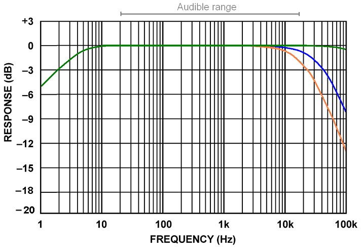
It can be bought in finished or kit form here.
Project Solstice v 1.0 is a low voltage amplifier. It can still reach 1W output power.

It is in the same ‘voltage range’ as the Sunrise and Starlight amplifiers but has the output stage of the Ember/Polaris.
This is a ‘basic’ amplifier with less features than the higher priced models but of course does have traits the other models don’t have.The Solstice does have autobias (like the Ember) but has manual heater selection (like all the other models). It doesn’t have the 3 colour LED under the tube base like Sunrise/Horizon and Ember but you can choose a single colour LED that can be replaced if desired.
The LED has a fixed light level but can be switched on/off via a jumper.
It also doesn’t have the input cap bypass jumpers nor does it have line-out sockets. The output resistance can be set in 3 steps.
Another feature is that it can handle an even wider range of tubes when the socket adapter is used. The amp also has a special jumper so tubes like the 12SN7 can be used as well.
Modifications to commercial amplifiers
Modifications to the Miridiy (Indeed, Bravo e.t.c.) amplifier.

Modifications to the Indeed G2 amplifier (step by step guide).

Modifications to the Bravo 12AU7 (written by Florian Gerard)
Little Bear B-1 portable tube headphone amp schematic and modification suggestions.
Musical Fidelity X-can v2 schematics including measurements and suggested improvements.
schematics of commercial headphone amplifiers
Panda headphone amplifier schematics:
Analog King tube buffer schematics.
Bravo Ocean hybrid amplifier, schematic and modifications.
Bravo V3 schematics (the tube hybrid with built in 3 band tone control)
Indeed G3 schematic
Reverse engineered from posted pictures, some part values not verified.
Larks – Guanzo NE5532 buffered headphone amplifier.
unverified values of some parts… :-X
Zigis portable amp first version (schematic only)
Zigis portable DC coupled amp with rechargeable battery (2nd version)
interesting links for no BS DIY audio
https://theslowdiyer.wordpress.com/
http://sjostromaudio.com/pages/

Great site. Your blog is very interesting.
Greeting Solderdude! I followed your mod instructions to improve my Bravo V2 look-a-like. I did pretty much everything including the heater mod. Everything works very well except when I plugged in the headphones there’s cracking noise and when I unplug the headphones same cracking noise appears! There’s also occasionally static noise on the right channel and when I touch the amp’s rca (ground) it’s gone and everything’s back to normal. I measured the headphone jack there’s no DC so why are there noises while plugging in and out?
Try cleaning the tube pins and checking if the tube socket contacts ‘clamp’ good enough.
That is often the cause of crackling in one channel.
Try wiggeling the tube in its socket to see if that is the problem.
Also you could try to clean the headphone plug and socket contacts.
These too can cause this. I don’t think it is a DC problem (because of the output caps)
Also these amps do pick up hum. When touching the RCA shields cures it you may have a groundloop issue.
Wow you’re absolutely right! There’s so much dirt in places you cannot see lol. The inside of the headphone jack and the tube pins are filthy! I cleaned everywhere before except those places I cannot see. But now after more throughout cleaning the problem is mostly gone! I suspected DC problem because I measured DC on the headphone jack before I replaced the cheap pot (with hundreds mV DC on that thing!) that came with the unit with a genuine Alps pot (maybe some DC creeped to the jack from the cheap pot because of close proximity?). I’ll replace the cheap headphone jack too as it’s likely a culprit of future problem. Thanks again Frans I learned to enjoy DIY (didn’t know anything about soldering until last month lol) because of your generous sharing of your knowledge!
Hi Frans, I got another pcb coming that’s similar to Bravo/Indeed (for 6DJ8) and I’d like to adapt it to run both 6DJ8 and 7DJ8. It seems that 7DJ8’s heater voltage is 7V? Is there simple changes to your heater circuit that can power both 6DJ8 and 7DJ8 adequately?
Btw my heater voltage using your circuit is always 6.125V, not 6.25V. Is there anything to be concerned here? Thanks!
For these PCB’s you may have to lower the resistor value of the LM317 a tiny bit (you can parallel higher values for instance) and ‘tune’ the heather voltage to the desired voltage.
When you use a small switch in series with those parallel resistors you can switch between the higher and lower heater voltage.
I actually meant the separate heater mod you recommended in your G2 guide: the Traco TSR 1-2465 is 6.5v and with the sb140 the voltage will drop to 6.25v. Is there simply way to make this separate heater supply work with both 6.3v and 7v tubes? Thanks!