Headphone attenuation adapter
published: Jun-29-2015, updated: Apr-16-2023

Passive Headphone Attenuator
 5 reasons to use an attenuator in the headphone cable.
- Some headphone amplifiers may have way to much power to safely drive high efficiency headphones like IEM’s or even ‘normal’ higher efficiency headphones.
When too much power is applied by accident (IEM’s or headphones lying on the table and the volume is turned up, accidentally, for instance) these headphones may burn out or get damaged voicecoils.
This can be an expensive mistake !
So for these types of headphones an attenuator that lowers the output power substantially is very welcome. - some headphone amplifiers may have a background hiss that becomes (annoyingly) audible with sensitive ear-/head-phones.
Attenuation at the input of the amplifier is pointless in this case as the noise is NOT coming from the source but the amplifier circuit itself and is not volume control dependent either in most cases.
Instead attenuation has to be performed at the output side of the amplifier to lower the noise voltage along with the music signal. This way the noise floor becomes inaudible again and the music sounds much better. - Sometimes the volume control only has a small ‘workable’ range where the headphone already plays pretty loud when the volume control is just barely turned up. Leaving the rest of the volpot range unusable.
- Some amplifiers perform (sound) better at somewhat higher output levels. In this case an adapter may improve sound quality.
- Some headphones really should (want) to be driven from a low output resistance source. A 33Ω or higher output resistance may affect the sound quality/tonal balance in a negative way. The adapter lowers the source resistance to around 3Ω but at the expense of a little more than -20dB attenuation.
A commercial version of this attenuator can be found HERE
Also iFi makes a similar adapter
I can also make this adapter for you in the same form as a passive filter in any attenuation between -10dB to -25dB attenuation versions with a wide choice of connectors to suit your needs.
In all the above cases a passive attenuator is needed/desired.
The difficult part here is that (Multi-Armature) IEM’s are usually very low impedance, generally between 8Ω and 32Ω and perhaps require a low output R of the amplifier in order to sound as intended. A high output resistance can quite noticeably change the sound !
Some sensitive headphones can also be relatively high impedance (up to 100Ω) but these are rarer and don’t really need a low output resistance to begin with.
Most multi-armature IEM’s have wildly varying impedances all across the audible frequency range.
Single driver ear/headphones usually just have a single impedance peak (in the ‘bass’ region mostly) and ‘upper treble’ region.
Because these low impedance ear/headphones have considerable impedance changes the frequency response (and thus tonal balance) will also change substantially when an amplifier output resistance above 1Ω is present.
Most modern phones/tablets/DAP’s/(portable) amplifiers have output resistances below 1Ω, though a few can be as high as 10Ω.
The reason for this change in tonal balance is not caused by the damping factor (as many still believe) but simply caused by voltage division.
To keep de frequency response as ‘flat’ as possible a low output resistance amplifier is essential.
If you are looking for more information on output resistances and the influence it has on the frequency response of (some) headphones you can find more info HERE
For this reason it isn’t wise to just mount a simple series resistance in series with the headphone as these increase the output resistance to substantially high values, 100Ω or more is not impossible.
Headphone adapters of 20Ω, 50Ω, 75Ω or even higher may work well with some specific IEM’s but most will not sound good at all with these ‘impedance adapters’.
So you probably need an adapter that provides a ‘decent’ load to the amplifier. This is because most amplifiers/DAP’s/phones don’t like to see very low impedances connected to its output.
It also needs to provide a substantial attenuation if we want to achieve goals like better volpot travel, protection against blowing it up and or noise reduction.
About 20dB attenuation is needed to achieve this.
10dB is close to being a 50% in perceived loudness (volume level or SPL).
20dB is thus about 25% in perceived loudness (volume level or SPL) and a very practical value.
We also need the adapter to have a low output resistance so the tonal balance remains the same as when the ear/headphone was connected directly to a low output resistance amplifier.
What the adapter will do
The adapter will always provide a load of around 35Ω to the amplifier. (Almost) regardless of how high- or low-Ohmic the connected headphone is.
Even when you short the headphone (make it 0Ω) the load the amplifier ‘sees’ is still 33Ω. So a short in a headphone cord will never short the amp.
The amplifier thus always ‘sees’ a constant resistive load of 35Ω
From the perspective of the headphone the numbers differ.
When you have an amplifier with say a 30Ω output resistance, the ‘source resistance’ that drives the headphone will always be be around 3Ω
When you have an amplifier with a 120Ω output resistance the ‘source resistance’ that drives the headphone will still be around 3.2Ω
When you have an amplifier with a 0Ω output resistance the ‘source resistance’ that drives the headphone will be around 3Ω
All headphones (regardless of their impedance) will thus always be driven by a 3Ω output resistance source, regardless of the output resistance of the connected source.
For sources with an output resistance above 10Ω this comes with a small penalty in the form of more than 20dB attenuation.
It attenuates around 20dB for all headphones when connected to an amplifier with an output R below a few Ω.
It attenuates around 26dB for all headphones when connected to an amplifier with an output R of around 30 Ω.
It attenuates around 33dB for all headphones when connected to an amplifier with an output R of around 120 Ω.
To create an attenuator that has these properties only 4 (cheap) resistors, a plug, socket and some wire is needed.
Of course you can buy these adapters but they are usually quite pricey.
If you have a soldering iron , a headphone plug, a headphone socket, some resistors, wire and some skill you can easily make these adapters yourself. If not it may not be too hard to find someone nearby who can make one for you.
So how about making one of these yourself…
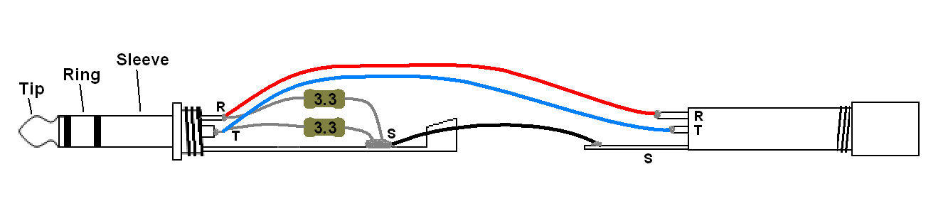
This attenuator is based on a TRS stereo Jack plug which can be 6.3mm(1/4), 3.5mm(1/8) or even 2.5mm.
TRS stands for: Tip, Ring and Sleeve. Tip = Left channel, Ring is Right Channel, Sleeve = ground (aka ‘common’).
You need a (male) plug and a (female) socket and can make a small extension cord.
The mechanical construction is something you have to figure out yourself depending on plug size, room in the plug etc.
You can even make a cable with a 6.3mm plug and a 3.5mm socket so you don’t need an adapter to connect a 3.5mm plug into a 6.3mm desktop amplifier socket.
You can try to mount the components in the plug itself if there is enough room for it.
If this is not possible you can make a small extension cord with the resistors externally in a small enclosure (for instance a short piece of electric piping with shrink tubing around it)

It is IMPORTANT to connect the resistors, that are connected to the Sleeve, directly to the sleeve of the male plug and NOT to the sleeve of the socket (upper schematic shown above)
If you mount the resistors OUTSIDE of the plug then the resistors that are connected to the Sleeve MUST have their OWN wires going from the resistor to the Sleeve of the plug. Do NOT combine these wires nor connect the return wires to the socket end. (lower schematic shown above).
Mounting these resistors somewhere in the ‘common’ wiring or on the socket creates a problem.
The reason for that is that the wire resistance of the used cable becomes a (substantial ?) part of the attenuation circuit in that case because the 3.3Ω resistors are very low in value. This could alter the stereo image.
Those low value resistors therefore must be connected directly to the Sleeve of the plug (male amplifier side).
The resistors can be carbon or metalfilm and don’t have to be wirewound or ‘special’ low inductance type. The 33Ω can be a 0.5W rated resistor, the 3.3Ω can be 0.3W to 0.5W.
Higher power ratings are not needed, not even when connected to amplifiers that can easily deliver 3W into 32Ω.
The reason you don’t need a higher power rating (Wattage) for the resistors is that the ear/head-phones used are high efficiency anyway. These headphones thus require very little power to play very loud.
Music signals do NOT consist of continuous power anyway but consists of very short peaks therefore the average power levels are quite low.
Small wattage resistors thus do NOT heat up even when the amp is playing loud so the power rating of small resistors is MORE than enough.
The adapter circuit shown above is suited for headphones ranging from 4Ω to 100Ω.
Using the output resistance of an amplfiier
When the amplifier itself already has an output resistance of around 33Ω you can even make an attenuator with just 2 resistors in the plug.
It does exactly the same as the attenuator above except the 33Ω resistors in the plug have now been replaced by the output resistance of the amplifier.
With amplifiers like the Musical fidelity v1 and v2, as well as some of these cheap Chinese Bravo/Indeed/Miridy amplifiers and also the Garage 1217 amplifiers set to ‘M(edium)’ output R setting the circuit below can be used to make an attenuator.
 In this case it is also very important to connect the resistors directly to Sleeve of the plug !
The adapter shown above can absolutely NOT be used with low output R amplifiers because the load resistance will be too low (< 3Ω)
The power rating of the 3.3Ω should be between 0.5W and 1W.
With these adapters you can safely connect sensitive ear-/head-phones to ‘potent’ and or noisy amplifiers.
The volume control range will also be MUCH better and the sound quality is NOT degraded.
In fact it may even improve as the noise level is lower and amplifiers usually perform better at higher output levels.
Balanced
The adapter as shown above will work with most equipment.
Just not with balanced outputs.
Normal amplifiers have a single signal (one for each channel) which is connected to a common return wire (often called ground)
Balanced amplifiers basically have 2 amplifiers which have the same signal on it but in opposite phase. The picture below illustrates the principle. The drawing is from www.tubecad.com which is a great source of info about amplifier designs.

A balanced amplifier has double the output voltage of a normal amplifier.
There is a small ‘but’ here because the maximum output voltage will only double when the output stage is able to deliver double the current as well.
Some devices simply aren’t able to do this and limit the max. output power due to current limiting of the amplifier design.
Most balanced amps (by design) would have to be able to provide double the current as well though.
With a single ended amplifier the output voltage, for instance, would be 1V (just a random number used here for illustrative purposes only) and this would be 31mW in 32Ω.
When the same signal is sent out balanced the ‘other’ amp that is now connected also will have a 1V output signal but in opposite phase.
This means: when one amp is at the ‘top’ of the signal there is +1Vrms and the other active amp at that same moment is -1Vrms.
The voltage difference between the 2 amp outputs (where the headphone is connected to) thus is 2Vrms. It is doubled in voltage. Double the voltage in the same resistance also means double the current.
Power = voltage x current so the power is 2 x 2 = 4 times higher = 128mW in 32Ω.
4x the power (= 2x the voltage) is an increase of 6dB in amplitude.
That is quite audible….
The output signal of the Left and Right channel thus are NOT connected like in normal headphone outputs.
Furthermore balanced outputs must NEVER have any of the Right an Left channels connected. You run a chance of blowing up the amplifier in question.
So to be able to use a headphone on a balanced amplifier you need to have 4 wires (2 pairs of 2 wires) which must be connected to a 4-pin connector or 2 pieces of 3-pin connectors.
There is a catch here which is that unlike ‘normal’ 3-pin headphone plugs (The so-called TRS Jacks) which regardless of size (2.5mm, 3.5mm or 6.3mm) have a pretty standard configuration. Tip = L, Ring = R, Sleeve = ground.
Below the universal schematic for a balanced headphone amp attenuator.
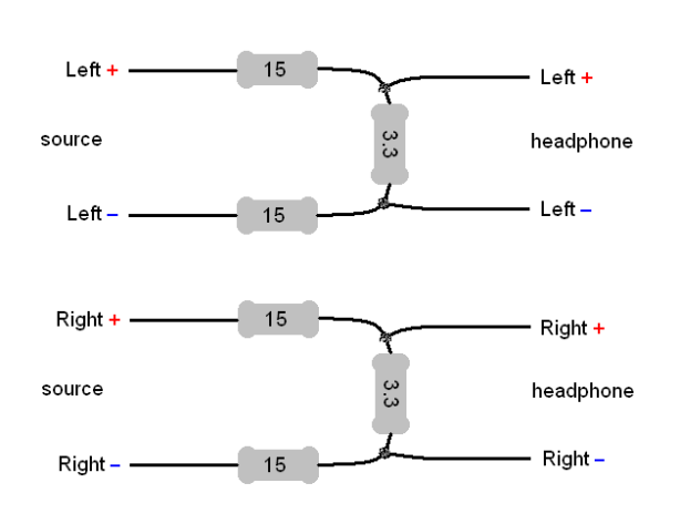
As can be seen there are no connectors specified. The reason for that is that there is no standard and not everyone uses the same pinning.
Source side is the amplifier side, headphone side is of course the side that must be connected to the headphone.
One could easily make an attenuator with just 2 resistors which will work just as well.
BUT the 2 resistors are there for 2 good reasons.
A: The balanced signal stays perfectly balanced
B: When accidentally the L and R load are connected the source will NOT blow up and is protected against over-currents.
Connectors
Now we know what the input and output signals are we must find out which connectors are used and what their pinning is. In other words which signal(s) should go on which pin(s).

Above on the left there is the well known TRRS jack (usually 3.5mm) which is found on many headphones these days. These are NOT used for balanced signals in general but there are manufacturers that (mis)use these connectors for this purpose.
NOTE: Never connect headphones that have a microphone and/or small remote in their headphone cord (those with a TRRS jack) to balanced sources..
The 4th connection in this case is needed for the microphone and/or remote control.
There are 2 ‘standards’ for these plugs CTIA (Apple devices) and OMTP (most other brands) so the remote/mic of headphone A may well work with device B but not with device C for instance.
When unsure about your connector THIS is a great website that might answer your questions.
So be careful with the TRRS jack.
When an attenuator is needed but the remote control is still needed below 4 schematics on how to wire this.
The top one is to connect an apple intended headphone to an apple device.
The one below that is to connect an android intended headphone to an android device.
The third one from the top is to connect an android intended headphone to an apple device.
The bottom one from the top is to connect an apple intended headphone to an android device.
While still keeping the mic/remote functionality and attenuate.

Below a few possible pinnings of gear with a 4 pin TRRS jack connected.

As most of these aren’t specifically for headphones below a listing of the 4 main configurations of this TRRS plug.

You need to find out what pinning is the correct one for the headphone AND is present on the amplifier/source.
The most common connector is the TRS jack (also in 2.5mm, 3.5mm and 6.3mm)
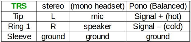
These are rarely used for balanced signals and in that case (Pono Player) you need 2 of those plugs, one for R and one for L.
One can never use a single TRS jack for balanced stereo signals but is almost always used for (single ended) stereo signals.
The mono plug only has a sleeve and tip and is often found on the end of a microphone.
It can only handle one signal (left or right for instance). 2 of these can be used for stereo signals (even balanced is possible with 2 of these plugs) but ONLY if the socket is a ‘mono’ socket as well.
NEVER plug a mono plug in a stereo socket. This could lead to damage of the connected source.
Another plug that is sometimes used for headphones is the 3-pin XLR (or mini XLR) or the 4-pin (mini) XLR.
The 4-pin XLR is suitable for balanced stereo signals.
You need 2 of those 3-pin XLR’s for balanced stereo headphones.
Below the most common configuration for 3-pin XLR plugs. Note that the pin numbering drawing of the XLR plugs above is valid when seen from the actual plug side.
When soldering wires onto these plugs you must realize what the pin numbering is on the solder side (mirrored from the plug side !).
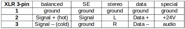
The most common usage is balanced. This is standardized and all XLR sockets in (pro)  audio equipment is usually connected that way. Most (balanced) high-end equipment often uses this plug. Sometimes the XLR socket is even combined with a TRS socket (see picture on the right).
Pin 1 is the ground. The pins (male connector) are all equally long but in the socket (female) the 1 socket is slightly longer. This way the ground is connected before the signal wires preventing loud ‘hums’ when plugging and unplugging.
The 4-pin XLR is not used that much in audio but is gaining in popularity for balanced headphones as you need just one (professional quality) connector.
Below the most common usages for this plug. The HIFIMAN connector is not an official standard but most manufacturers use this pinning.

Connecting the attenuator
Once you have determined what plug(s) you need and how they must be connected you can create an attenuator that has the same properties (in impedances and damping) as the G1217 adapter except for balanced amplifiers headphones ONLY.
It can NOT be used with single ended (3 wire) headphones.
In case one makes a mistake with wiring the headphone or accidentally or connects a 3-wire (TRS jack) headphone you can rest assured the amplifier/source will not be destroyed in the process. The ifi one does not offer such ‘protection’ when used in balanced mode.
Because of the many possible configurations and connectors such an attenuator has to be custom made. Some manufacturers offer converters or conversion cables from one plug to another. Beware that here too you will have to pick the right one for the job.

Hi, Solderderdude. Thank you for the well writen article, it’s very comprehensible, but i’m planning to use a 5,6 and 56 ohms resistors. In that case, should i use the same wattage rating of the 3.,3 and 33ohms? Thank you.
0.5W is fine, the 5.6 ohm can be 0.25W.
Hi Solderdude. I intend to make one adapter for LG phone, they are notorious for their Automatically scaled power where if you headphone is low impedance the output power will be small. Can I make one adapter with let say 100 or 150 ohm for the phone to see and 3,3ohm for the IEM? Or 35ohm is already enough to make the phone send more power? Thank you very much
Won’t work. The phone may double its output but the attenuator will attenuate far more than what the phone does. So will adding a single resistor do the same. You will get a higher output voltage but due to voltage division this will be undone.
The only 2 ways to go louder is buy a more sensitive headphone or use an amplifier.
ok… I though there might be away. Thanks
can you let me know about the balanced attenuator you posted here? I’m really curious about this one. normally i see attenuators treating the cold side as a ground and performing SE attenuation. Wondering if you can give me some background on how much attenuation it offers and what load it presents to the amp. My ZMF Auteur is hissing on my Cayin HA-6a and i’m only able to use 1 step of the volume controls 😦
Electrically the balanced version has the same load and attenuation as the SE attenuator.
That is if you take the value of R1 (in SE) and put half of those in each signal path.
In balanced connections, when we are looking at immunity for extraneous signals, the proposed balanced attenuator adheres to that principle and lowers + and – output signals the same amount where the SE attenuator (with not coupled – connectors !!) would have imbalanced electrical signals.
The end result (attenuation and load as seen by the amp and headphone) are exactly the same though. The balanced attenuator only is more ‘technically’ correct from a balanced signal p.o.v.
Hi,
The volume control on my Pro-Ject Head Box S headphone amp only needs to be turned on a fraction to drive my Philips Fidelio X2 HD headphones to a fairly loud level. ( but I would like to listen at low levels in the evenings) !
The Pro-Ject states to use headphones greater than 30 ohms. Gain= 11dB. S/N = 112dB at full output.
I think the Philips headphones are 30 ohms also. I guess if I connected a pair of 200 ohms headphones then the volume control would be at the half way point for normal listening ?
Which example of your attenuator circuit should I use (the 1st or 2nd example ?).
What value of resistors should I use to achieve the above ( to emulate circa 200 ohms headphones)..
I hope the above will be possible.
Thanks for your help.
Peter.
X2HR is 30 ohm.
The first one should be used. Whether or not it is the top or bottom one depends on where you can mount the parts.
The 33ohm can remain the same value. Depending on how much attenuation you need to get the desired volume control range the 3.3ohm resistor may be anything between 10 and 3.3 ohm.
With 10 ohm you have less attenuation, with 3.3 ohm the most attenuation.
The amp will ‘see’ a 35 ohm load which is fine for this amp.
Many thanks for your quick reply ! Brilliant !
I will try it as you suggest, hopefully this will solve my problem, I didn’t want to buy a replacement amp or headphones as I like the sound they produce.
I’ll let you know how I get on….
Cheers,
Peter.
Hi, Solderdude. Amazing article, many thanks. I have some questions, would be grateful for some help.
I have a (partially diy) music player, and it has two 3.5 sockets, PO (Phone Out) and LO (Line Out). I don’t really need my Line Out (why would anyone really need LO on a portable device anyway?), and my PO (the one I use for listening to music with my IEM’s) has hissing noise when listening with high sensitivity low impedance IEM’s.
Making an attention adapter is cool, but I want to build in the attention scheme Into my player (less chance of breaking the adapter, less cable problems, more convenient).
So what I was thinking, is that I’d disconnect (cut the traces of the printed circuit board that lead to..) the Line Out socket, since I don’t use it, and just connect the resistors to the PO, then wires to the LO, and use the PO for when I don’t want to use the attention adapter, and the LO when I do want to.
Would that work? Will the fact that the attenuation circuit is always connected mess up the sound of the Phone Out? I mean, you said that “The amplifier always ‘sees’ a constant resistive load of 35Ω”, and then I’ll be adding my headphones impedance to that (if I understand correctly, parallel impedance of 35 (adapter) +, let’s say 32 (iem), that’s 1/R=1/R1+1/R2 => R≈16.7 Ohm)… Is that bad, and is there any way to fix that, so I’d be able to use my usual PO without attenuation and my LO with attenuation?
Also, “The 33Ω can be a 0.5W rated resistor, the 3.3Ω can be 0.3W to 0.5W”. Are those the minimal values, or also the maximum? If I don’t find such low wattage, can I use higher? (pardon if this is a dumb question)
And carbon vs metal film. After doing some reading, I concluded that most agree that metal film is better, however finding any radio parts (resistors, capacitors, etc.) is difficult in my country. Will carbon film be good enough? I really don’t want to lose audio quality or get any more added hiss (that’s what I’m trying to get rid of).
P.s. my current configuration looks somewhat like this: my op-amp is OPA1622 which gives 100mw at 32 Ohm load (I think, not very good with datasheets), since the player is DIY I can set the output resistance myself. Currently I’m using 2.2 Ohm resistors for the source output on the PO socket. I don’t want to go higher, because of the 1/8 impedance rule (at least that was what I was thinking when choosing the output resistance). I can make it anything from 0 to 100 (or more, whatever SMD resistors I can find), so if you think I should change it, let me know. However as I mentioned above, I’d like to keep the PO without attenuation and LO with. That’s because I have some 32 Ohm iems that practically don’t have any hiss through the PO socket, but I also have some 32 and 16 Ohm IEM’s that have terrible hiss (and I want to use them with the attenuated LO socket).
Sorry that this turned out so long, but last question. Are there any drawbacks to using this attenuation thing? I just mean, I’ve honestly never heard of such a thing before, and it sounds too good to be true. Less noise and no compromises? If so, then why don’t companies build in this kind of thing into phones/players/amps that have hiss, or even straight into cables of high sensitivity+low impedance headphones/earphones?
I only use the line-out of my (FiiO) players into a headphone amp.
I can understand for many this won’t be the case.
Yes, you can cut the wiring to line out and turn it into IEM output.
BUT… you would have to realize that this circuit will always load the internal amplifier with about 35 ohm even when not in use.
When you use the normal HP out and plug in a 32 ohm headphone your amp section will thus be loaded with 16 ohm as you already concluded.
The OPA1622 is kind of limited to 70mA (110mA top) so 1.1V on the PO with 32 ohm load = 40mW
When the attenuator were not there 2.2V (160mW) would be possible assuming enough voltage is present.
When you hear a lot of hiss you will need 20dB attenuation.
As you can see in calc. above that the resistors would be required to handle about 0.1W so even the smallest resistors will do. Of course you can use larger wattage resistors but these are bigger in size.
I see.. I guess I’ll still make my LO into an attenuated headphone out, even if I lose my normal headphone out in the process, but I’ll first try to make a normal attenuator and see how it works. Last questions: does the attenuator use more battery (sorry if this is a dumb question)?
I don’t think it will lower playing time. The extra consumed power will be a few mW only.
Can you connect an attenuator to an attenuator? 2 in a row? What will the result be? Double attenuation, or is that not how it works? And will the wires from the first attenuator mess with the “connect to sleeve” rule for the second attenuator?
If this is possible, then what numbers should I use for the resistors, to achieve 20dB attention with both attenuators, and half that with just one? (so I could build one into my player and use it for more power hungry headphones that have minimal hiss, and plug in the second for low impedance high sensitivity IEM’s)
Yes, you can use 2 in a row and get 40dB attenuation. That is a LOT though and don’t know which headphone would need one. Depending on the sensitivity of the used IEM the first attenuator will dissipate a lot of power.
When you really need -40dB or -30dB I would recommend to just lower the value of the smallest resistor.
An attenuator with just 10dB attenuation may have an output resistance that may become too high for some IEM’s.
Is it only necessary to connect the small resistors directly to the male plug? Can the 33Ohm ones be connected later?
Say I use an 8 core cable. Can I connect the 3.3Ohm resistors straight to the Sleeve of the male jack, then to cables; the 33Ohm ones to cables that are connected to the male Ring and Tip respectively, and then connect the wires from the 3.3Ohm resistors and the 33Ohm resistors themselves in the female socket (and just connect the male->female sleeve with 4 wires)? So the 3.3 resistors will be housed in the male jack, and the 33 resistors in the female socket. Can I do that?
Yes, that’ll work fine and you can spread the resistors over the plug and socket.
You will also have to wire the grounds of both connectors via wires. Use as many free wires as you have left in the cable in parallel for the ground.
Can the 3.3Ohm be 0.25W rated, or is that too low? I can only find 0.25 or 0.5, and I’m afraid 0.5 might not fit in the jack. 0.3 are unavailable here
0.25W is not an issue. it will probably only dissipate a few mW.
Thank you so much for detailed instruction. This circuit works so well!
Needed it primarily for a Sony DD3 Walkman and some really sensitive earphones.
It was a bit challenging to fit all the components in a small jack plug but I managed somehow 🙂 My hand is not as stable as it used to be haha.
Used Neutrik plug and socket, bought of ebay for £2 a piece. Resistors are also pretty cheap, used 1/4W for the 3.3ohm as they have smaller footprint. Works well so far.
Would be happy to share photos but not sure if that wouldn’t flag spam.
Hey Solderdude I left a reply here around 8 months ago (I don’t mind if you don’t remember me) I’ve been busy and never got a chance to do this. I’ve been trying hard to find resistors online with the exact resistance you recommended, but then it occurred to me. POTENTIOMETERS. I mean, with a potentiometer you can adjust the resistance to always make it just right on top of not having to find specific resistors (2.2 ohm is quite rare)
So is there any way to implement this? Can I just put a potentiometer on the negative output? That would be way easier. Or would that mess with dynamic range and sound quality? Because I still don’t understand why you didn’t recommend to just use a single resistor.
Thank you in advance!
My memory is bad. I meant 4 months ago.
Potmeters exist (wirewound for higher power or trimmer pots) in values of 10, 20, 25 ohm and 50 ohm. You could use those but not only the amplitude will vary but also the load the amplifier sees as well as the virtual output resistance of the amplifier.
Better would be an L-pad. These exist in 16 ohm. One could add a resistor.
The advantage of an Lpad is that the load the amplifier sees remains constant.
Hey Solderdude,
first thanks for your awesome work!
Is it possible to build this with higher load for the amplifier, maybe 60-80 Ohm and something around 1 Ohm for the output?
Yes, just use the same ratio. The output R the headphone ‘sees’ also increases with the same ratio.
Hi Solderdude. Great work. I’m wondering if you have had any experience using this circuit with valve output amps. I was thinking the 32 ohms impedance connected to an 8 ohm output transformer secondary would reflect a very high impedance onto the output tube anodes. Maybe 16 Ohms would be a better impedance for valve amps, albeit greater power dissipation in the resistor divider?
It depends a bit on the amplifier topology. But yes you can make the same attenuator using 15 + 1.5 ohm resistors or even 10 + 1 ohm. In those cases the power rating should be higher. Especially the higher resistance one.
If I use 33 Ohm and 10 (instead of 3.3), how does that change the output impedance (the impedance the headphones will see)? Will it still be around 3, or..? I’ll be using it with 16 Ohm in ears. I just don’t want to attenuate too much in order not to loose to much power
You will get 16dB attenuation and the output resistance will become 5.2ohm.
What output resistance will I get if I use 5ohm instead of 3.3? I’d like to keep the output resistance below 4
When you change the 33ohm for 18 ohm and the 3.3ohm for 4.7ohm you get -15dB attenuation.
The amp will ‘see’ 22 ohm and the headphone will be driven from 3ohm.
Thanks!
I have been using the iFi ieMatch. At times I have felt has affected the sound positively, other times negatively. I am not sure what difference is really there and what is just mind over matter. How exactly could distortion/alteration be introduced by these devices?
When you have too much attenuation you might be clipping the amplifier. When severe enough this will give distortion.
By themselves, as they are just linear resistors, they cannot introduce distortion.
Also, with headphones/earphones with a substantial impedance variation you can introduce (or improve) tonal balance of said headphones.
Is there any specific reason why you specifically chose 33 and 3.3 Ohm, not, say, 10 and 1?
Yes, most audio equipment has no issues driving a 35 ohm load but many amps would be in trouble (current limiters) driving a 11 ohm load. Also most output stages distort more in lower impedances.
The ifi one is 16 ohm which also is a kind of low load resistance.
So it’s a balance between easy enough load, attenuation and output resistance of the attenuator.
How much attenuation would I get with 30 and 3.9 Ohm resistors? And what would the output be (what would the headphone see)?
Attenuation would depend on the connected headphone. When looking at an impedance range from 12 ohm to 120 ohm attenuation would be between -21dB and -19dB and output R (assuming the source is close to 0 ohm) = 3.45 ohm
Hey solderdude, Amazing article but I can’t find the 3.3ohm resistor can I use 10ohm resistance instead. I have kz edz pro iem, plz help me about this
When you use 3x 10ohm in parallel you get 3.3ohm.